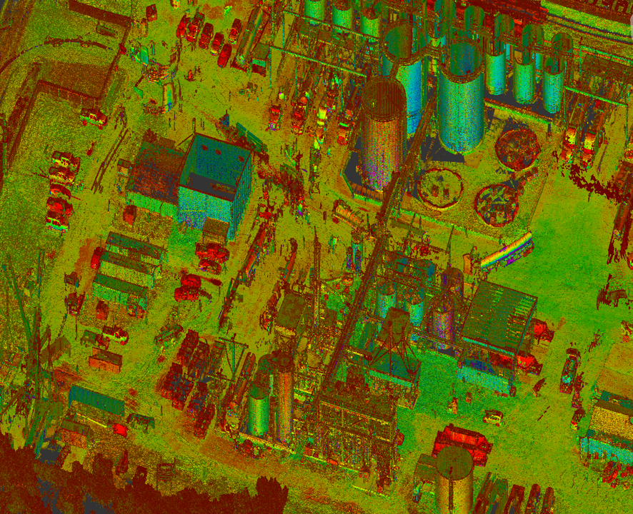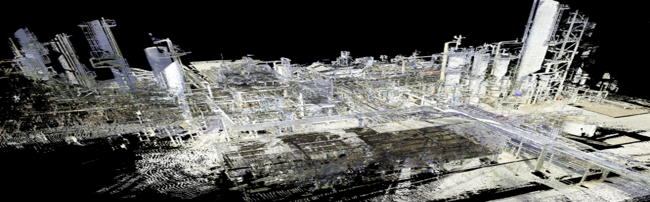
Full unit scanning comprises of data capture within a boundary or battery limits of a process unit(s). This type of scanning ranges from general scanning to more detailed scanning for detailed design purposes. An advantage from large unit scans is that it allows for digital planning capabilities before large turnarounds or maintenance projects and can be collected more quickly since less detail is usually required. Software capabilities allow for work packages to be integrated digitally and shared. This is great to reduce time in the field and to involve parties in the planning process from across the country or globally.
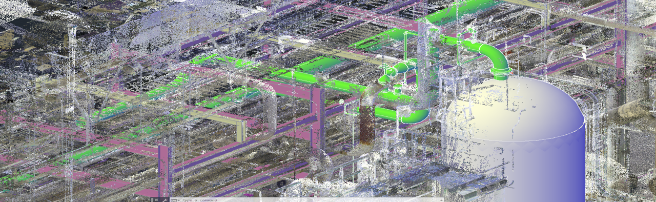
A pinnacle for laser scanning technology has been the use in aiding with pipe design. Traditionally, designers will spend countless hours in the field trying to field verify existing piping or conceptual routing that can often be elevated or in hard-to-reach areas. Laser scanning is a desired solution because it offers a digital rendering of the areas of interest within 1/8” accuracy tolerances making it a great tool for detailed design. Scanning also allowed designers to overlay their conceptual models with the scan to see how piping systems will fit, a great visual aid to provide confidence in the design and for presentation purposes for clients.
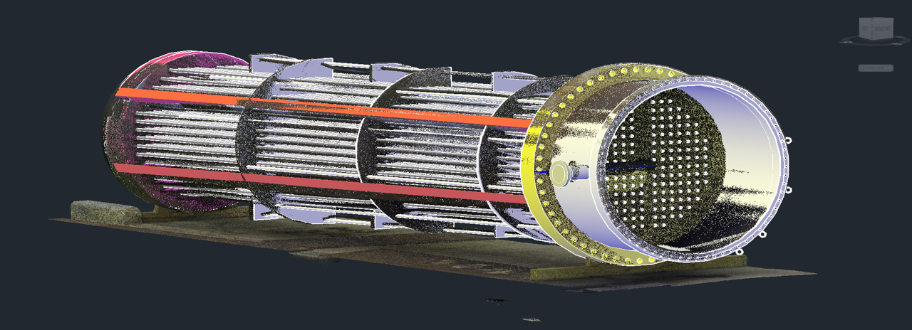
Shores M.D.S Laser Scanning Group has recently completed several scanning projects to aid with the aid of new design and re-engineering of older equipment and components that had little to no information dimensionally for the purposes of fabrication. Often times, this required a quick response last minute as a component may only be pulled for a period of time before being reinstalled. Scanning allows for a quick digital rendering of these components to be archived to aid with this process. Below is an example of a vertical fixed tube exchanger bundle that was pulled and that needed to be documented for redesign and fabrication. Shores was able to scan the bundle and integrate a design model from our Dimensional Control Automet software to backcheck the fit of our conceptual model. This provides confidence in the design and a great visual for the client.
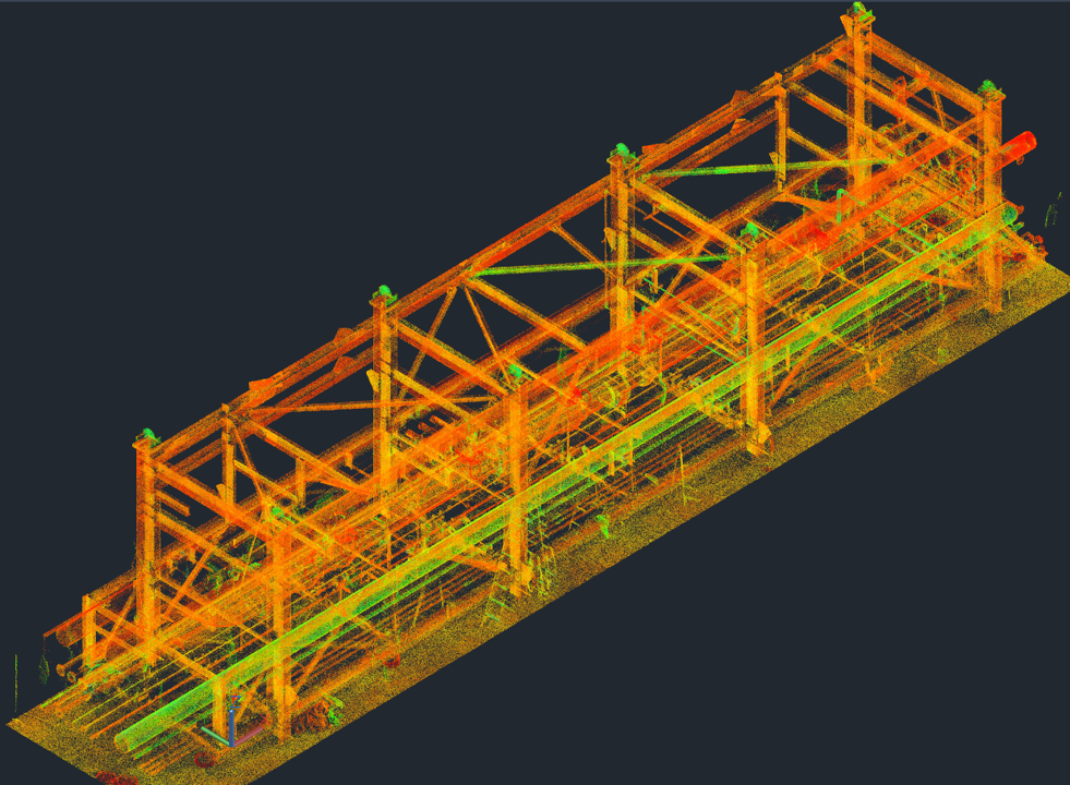
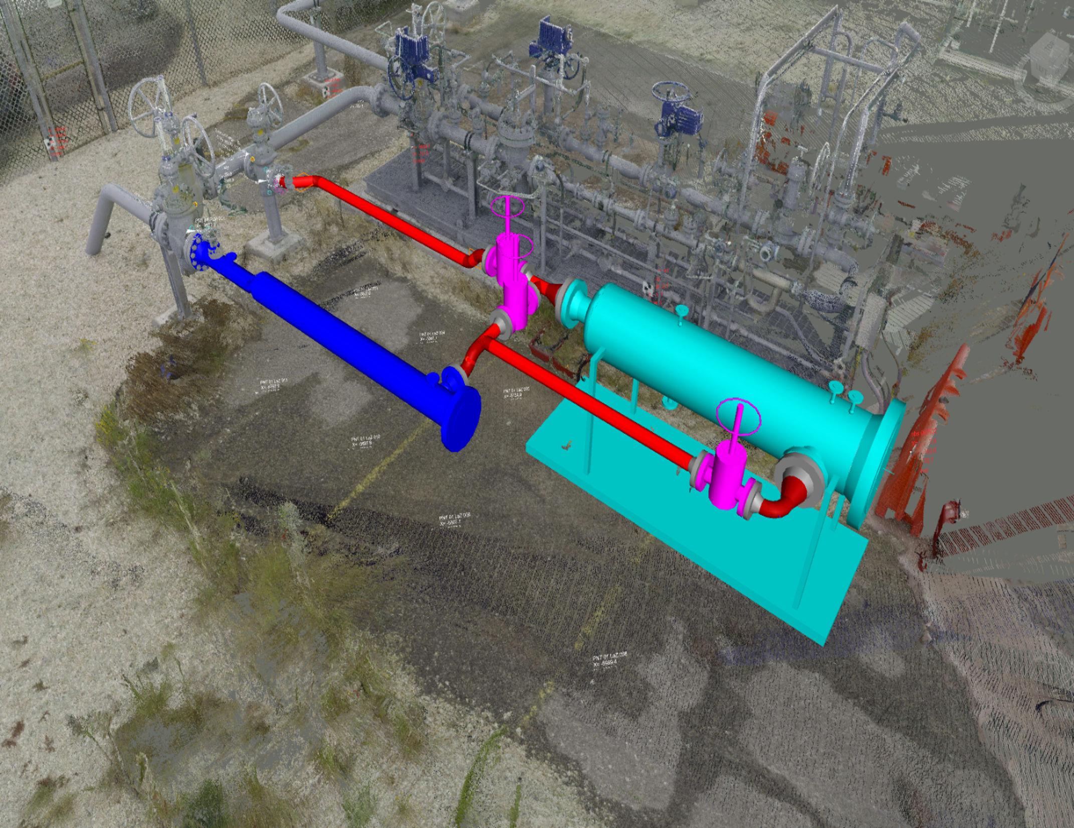
Module verification is an important tool to ensure that module fabrication adheres to design constraints. Shores has recently verified several piping modules to ensure no twisting in steel and to ensure that tie-point projections matched between the as-designed coordinates and the as-built coordinates. This process involves laying out the conceptual design projections at the coordinates provided by the client. We then scan the modules and overlay the scan to check the as-built coordinate projections. Deviations are noted and a report is submitted to the client. Verification provides a peace of mind knowing where a module stands prior to transportation and install.